The second PIC prototype addresses the issue of high voltage drop in current loops caused by the industrial optocouplers used in the first full industrial prototype. While this problem has been resolved, only one manufacturer currently offers an industrial optocoupler that meets all PIC specifications. This dependency is unacceptable for a system with a projected lifespan exceeding 10 years.
Concept
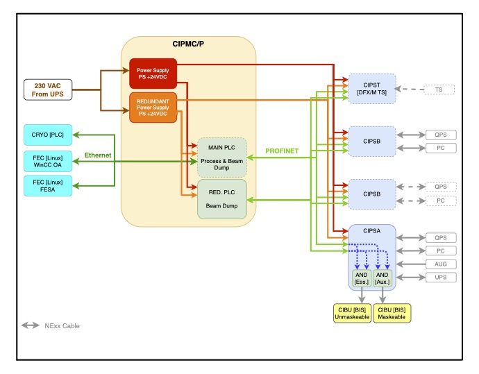
The PICv2 system is built on PLC technology and features custom-designed electronic interfaces. At its core is a master crate (CIPM), which houses two Siemens S7-1500 family CPUs and a redundant power supply capable of supporting any entire PIC configuration. The master crate connects to distributed I/O slave crates via two independent PROFINET-IO fieldbuses, enabling communication with the Quench Protection System (QPS), Power Converters (PC), the general emergency stop system (AUG), the Uninterruptible Power Supply (UPS), and the Beam Interlock System (BIS).
The system architecture dedicates one CPU to the full process control, while the second CPU is exclusively reserved for beam dump functionality.
To interface with all surrounding systems within an LHC powering subsector, only two types of slave crates are required: the CIPSA and CIPSB. Additionally, the CIPST crate, designed to interface with thermal switches from the DFHX and DFHM at LHC points 1 and 5 (HL-LHC), completes the PICv2 hardware portfolio.
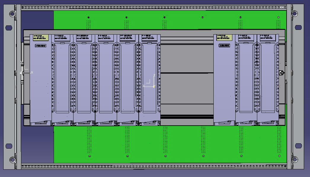
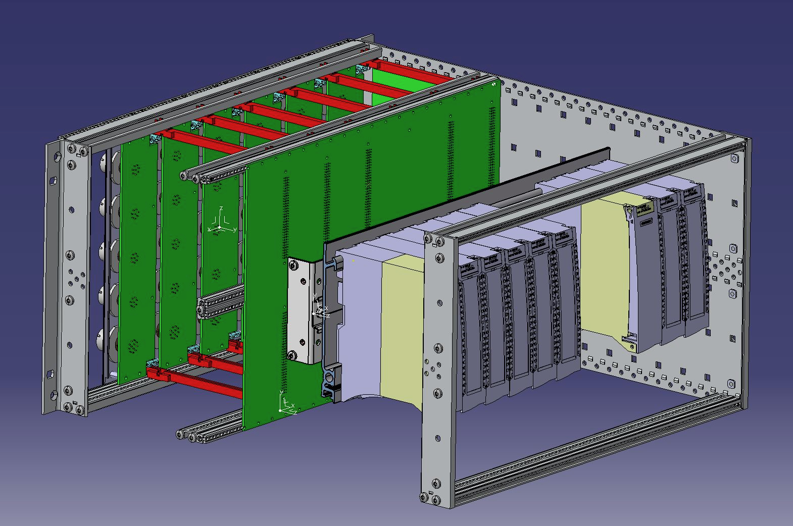
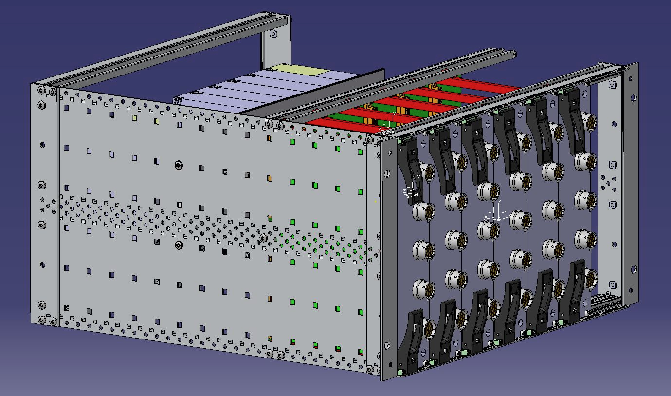
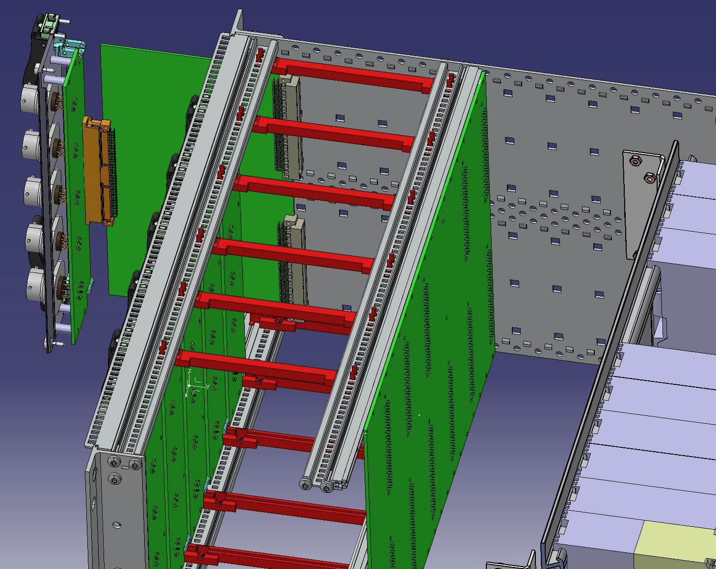
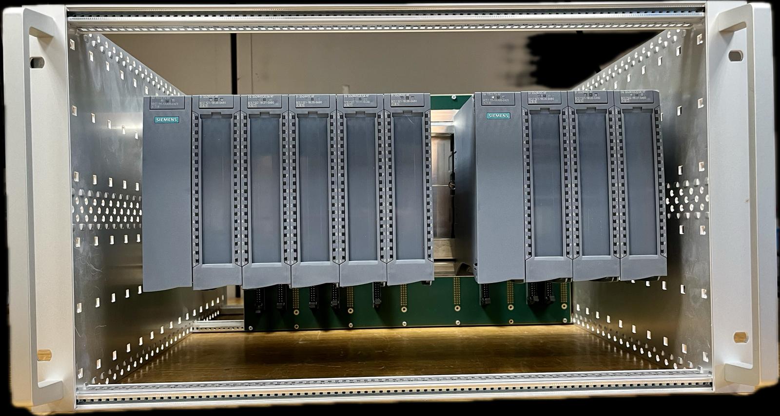
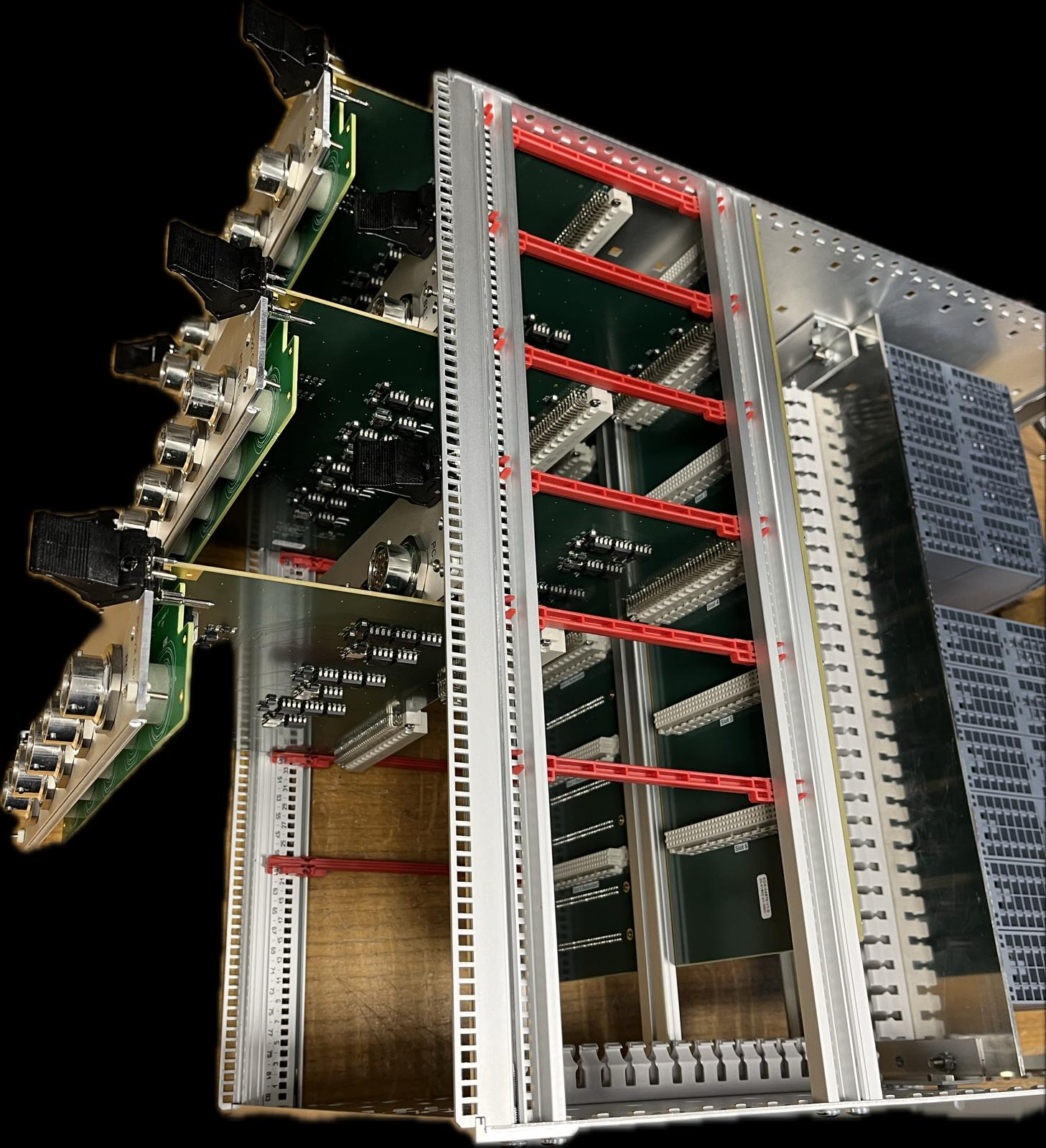
All crates are designed from a standard 6U, 19" crate from SCHROFF. In particular, the CIPSA and CIPSB house two Siemens ET200MP I/O deported slaves (for redundancy) on the front connected to sliding tailor-made electronic boards on the rear through an electronic backplane and flat cables.
 |
 |
 |
 |
|
|
|
|
|
||
|
CIPSB slave crate design |
||||
Control Architecture

Interface Cards
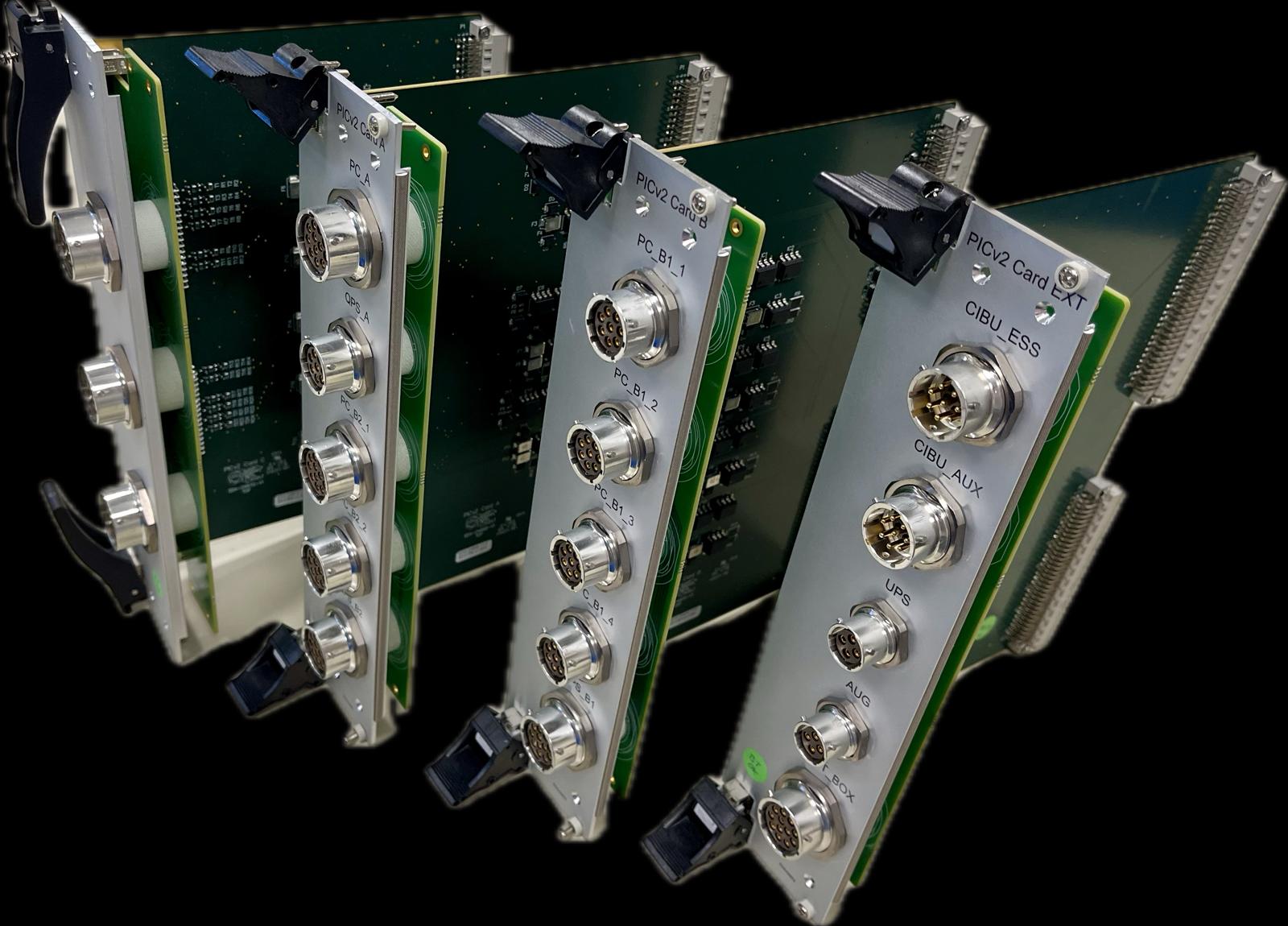
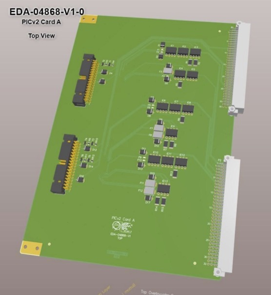
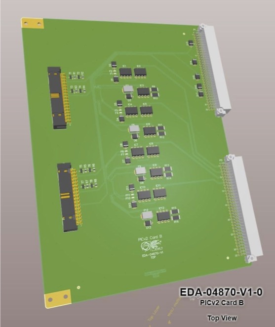
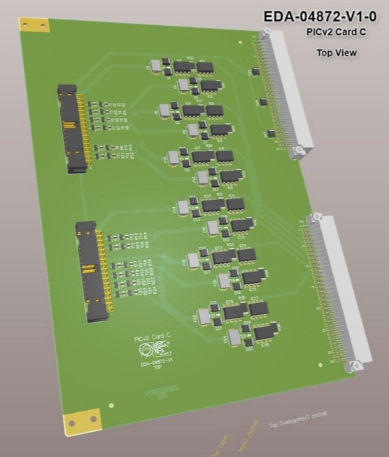
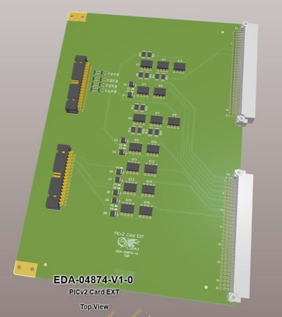
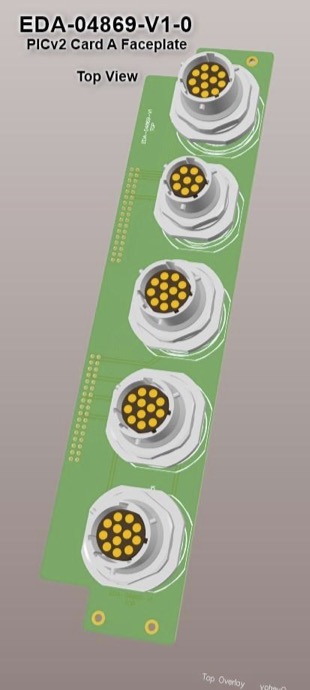
There are 4 different sliding electronic cards, namely A, B, C and Ext cards; all complemented by their dedicated faceplate.
| Card | Faceplate | Component | Description | EDMS File |
 |
|
Card A |
Interface board for: 1xA type circuits 2xB2 type circuits (Common QPS cable) |
Interface board:
Faceplate: |
 |
|
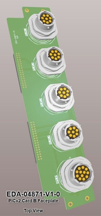
Card B |
Interface board for: 4xB1 type circuits |
Interface board:
Faceplate: |
 |
Faceplate variant C1:
Faceplate variant C2:
|
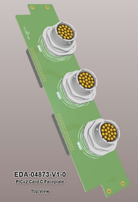
Card C |
Interface board for: 12xC type circuits |
Interface board:
Faceplate Variant C1:
Faceplate Variant C2: |
 |
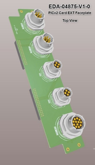 |
Card EXT |
Interface board for: 1xAUG 1xUPS 1xCIBU (Maskable) 1xCIBU (Unmaskable) |
Interface board:
Faceplate: |
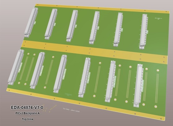 |
Backplane for slave crate TYPE A | |||
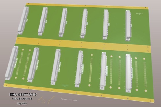 |
Backplane for slave crate TYPE B |


Automated Test Bench for PIC Interface Cards
The Powering Interlock Controller (PIC) relies on special electronic cards to safely connect with other systems. To ensure these cards (EXT, A, B and C) are built correctly, we are developing a fully automated test bench that checks every component and connection. Using advanced measurement equipment and a custom controller, the system makes testing fast, reliable, and consistent.
To guarantee reliability, every component on these interface cards must be correctly mounted and of the right type and value. The new automated test bench has been designed to ensure this quality systematically.
Built on a PXI system from National Instruments and programmed in Python, the test bench provides a fully automated validation of each card.
The setup consists of a PXI crate connected to a dedicated PIC slave crate, which is fitted with a Test Controller Card (TCC) in place of the usual backplane. The TCC integrates all the necessary electronics—relays, protection resistors, and connections to the PXI measurement and power modules—while preserving the sliding mechanism for easy insertion and testing of each card.
This approach ensures that every PIC interface card is thoroughly and consistently verified before being deployed.
| Card | Component | Description | EDMS File |
 |
TCC |
Test Controler Card: To interface cards EXT, A, B, C with the PXI crate |