Powering Interlock Controller (PIC)
Protecting the LHC superconducting circuits and ensuring safe beam operation
Role and Context
The Powering Interlock Controller (PIC) is a key element of the LHC Machine Protection System. Its role is to ensure that superconducting circuits are only powered when all required conditions are fulfilled, and to trigger protective actions when these conditions are no longer met.
The PIC receives and processes interlock signals from several systems, including the Quench Protection System (QPS), Power Converters and Cryogenics. Based on these inputs, it determines the state of the Powering Permit, which directly governs whether a circuit can be powered or must be stopped.
In addition to controlling the powering authorization, the PIC interfaces with the Beam Interlock System (BIS). For critical faults, it requests a beam dump to ensure that the energy stored in the beam does not lead to equipment damage. These actions are performed with deterministic behavior and reaction times compatible with machine protection requirements.
The PIC therefore enforces a consistent link between equipment conditions, powering authorization and beam operation. It ensures that unsafe situations cannot persist and that all protection actions are applied in a coherent and predictable manner across the machine.
Hardware
| Image | Component | Description | Schematics/Mechanics | |
|---|---|---|---|---|
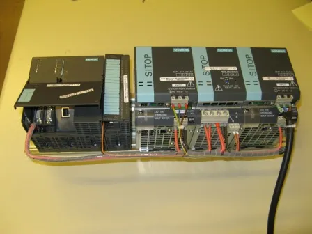
| PLC | SIMATIC S7-300 CPU 319-3 PN/DP: in charge of running the core program of the PIC. DIGITAL INPUT SM 321: reads the status of the power supplies. SITOP REDUNDANT POWER SUPPLIES: ensure redundant voltage supply of the PLC. | ||
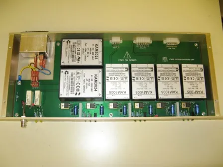
| CIPS | POWER SUPPLY UNIT: containing redundant modules to provide the required +5V and +24V to the electronics. | EDMS | |
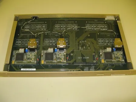
| CIPA | ANYBUS UNIT: contains HMS Profibus slave modules to share interlock signals between the patch panels and the PLC. It also hosts a CPLD matrix to provide redundacy and fast response for beam dump request propagation to the Beam Interlock System (BIS) | CIPAA | CIPAB |
| CIPPA | TYPE A – PATCH PANEL: provides interface with power converters and quench protection systems. It contains the following interface families: 3A-1B1-1B2-2C | EDMS | |
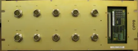
| CIPPB | TYPE B – PATCH PANEL: provides interface with power converters and quench protection systems. It contains the following interface families: 8B1 | EDMS | |
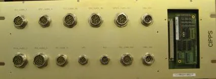
| CIPPS | TYPE S – PATCH PANEL: provides interface with power converters, quench protection systems, uninterruptable power supplies, arret d’urgence and beam interlock system. It contains the following interface families: 1A-2B2-5C-special | EDMS | |
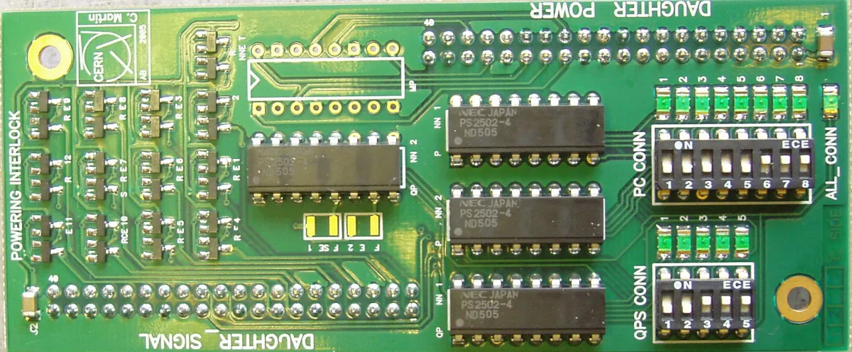
| CIPI | DAUGHTER BOARD: Generic board for patch panel which provides current sources to the loops and optocouplers for reading purposes. | EDMS | |
| CIPPM | TYPE M – PATCH PANEL: provides interface to signals that arrive in packages (i.e. signals for converters of type C interfaces arrive in packages of 4). | EDMS |